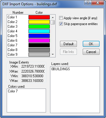
AutoCAD DXF Import Options Dialog
The Import Options dialog allows you to specify options which determine how information in the file is imported.
AutoCAD-compatible Drawing Exchange Format .DXF files contain information describing graphical objects, such as areas, curves, points and text. The DXF Import Filter reads DXF files and structures the information in a form usable by the application.
Customize import options in the DXF Import Options dialog.
Color Number
DXF files contain no direct color information, but use color numbers (1-255) instead. There is an adhoc standard association of colors with the first 7 color numbers: Red, Yellow, Green, Cyan, Blue, Magenta and Black. By double-clicking on items in the COLOR list box, you can change the color associated with a specific color number.
Default
Pressing the Default button will assign a default set of colors to each color number.
Apply View Angle
If any viewing angles have been applied in AutoCAD, check Apply view angle to preserve these settings. The unrotated coordinates will not be preserved if this box is checked.
Skip Paperspace Entities
To import only graphical entities from AutoCAD's 'modelspace' and skip importing entities from 'paperspace', check the Skip paperspace entities option. If this option is not selected, entities from both 'paperspace' and 'modelspace' are imported. This option is checked by default.
File Info
Click the File Info button to display the file information concerning the image extents, color numbers used and layers used in the .DXF file. The dialog extends to show this information, as shown above.
Colors Used
Selecting a color number displayed in the Colors used list box automatically selects that color number in the Color list box.
Layers Used
Double-clicking on a layer displayed in the Layers used list box displays the Layer Name dialog, showing the graphical entities present in the layer and a check box showing whether the layer is marked frozen (invisible) or not.
AutoCAD Entities
The point, line, and polygon AutoCAD entities are currently supported.
Point
Created with the AutoCAD POINT command. The current point attributes are used; only the position is extracted from the DXF file.
Line
Created with the AutoCAD LINE command. If subsequent LINEs are connected, they are concatenated into a single curve. If the first point equals the last, an area is created instead.
Polygon
Created with the AutoCAD PLINE command. The flag field is read to determine if the polyline is closed or not. If the first and last points are equal, an area is created; otherwise a curve is created. In general, the PLINE command is the most efficient
See Also
AutoCAD DXF Import Automation Options